ESPHome Energy Meter
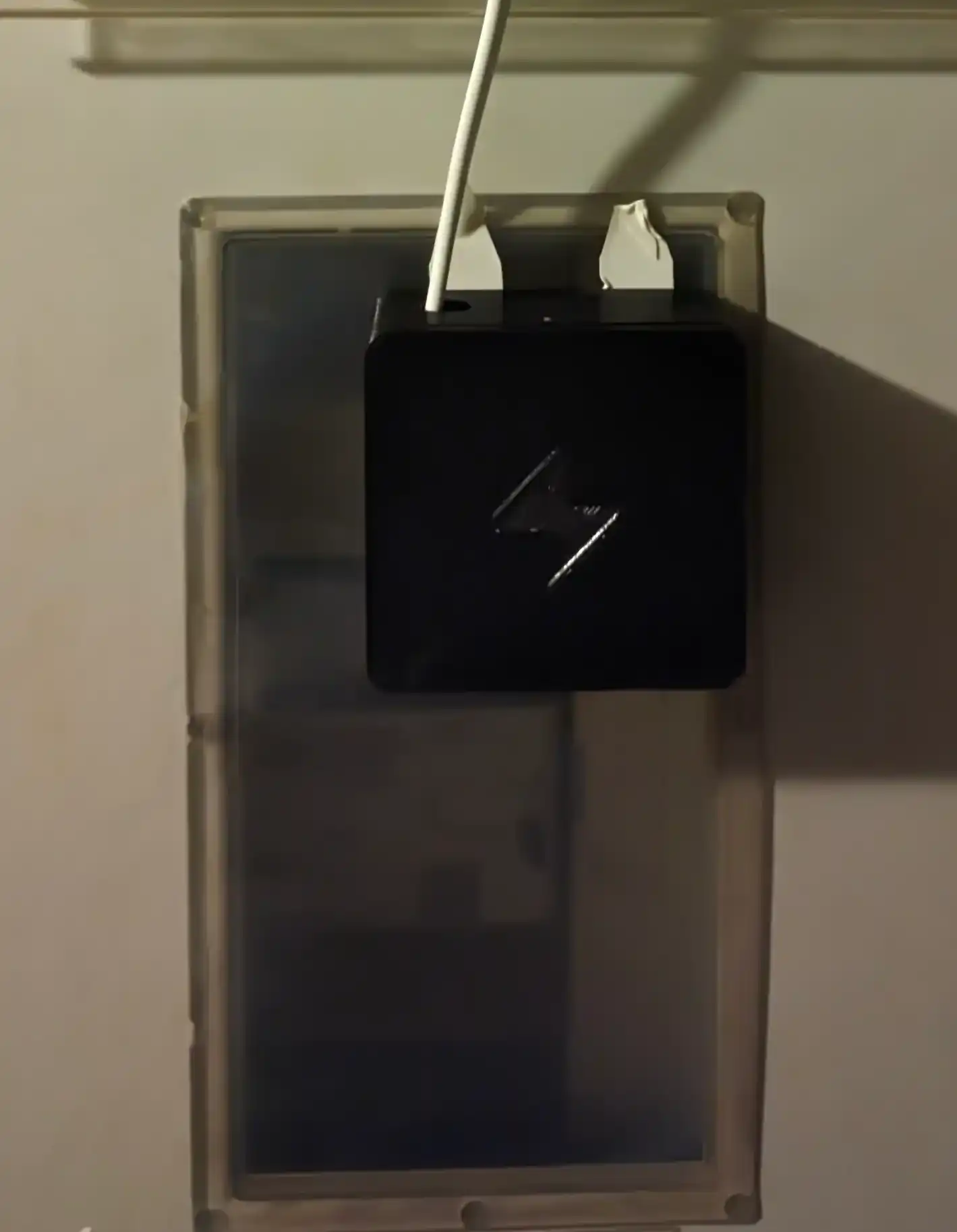
These are the source files for my ESPHome Energy Meter project, a battery-powered device that reads electricity consumption data from a digital electricity meter and sends the data to a Home Assistant server (or any other MQTT-compatible platform) at configurable intervals.
The basic idea is to regularly read the SML data transmitted by the electricity meter via its infrared LED, decode the data, and then send the decoded values to an MQTT server via WiFi. These values can then be integrated into Home Assistant using the MQTT integration.
📋 Required Components
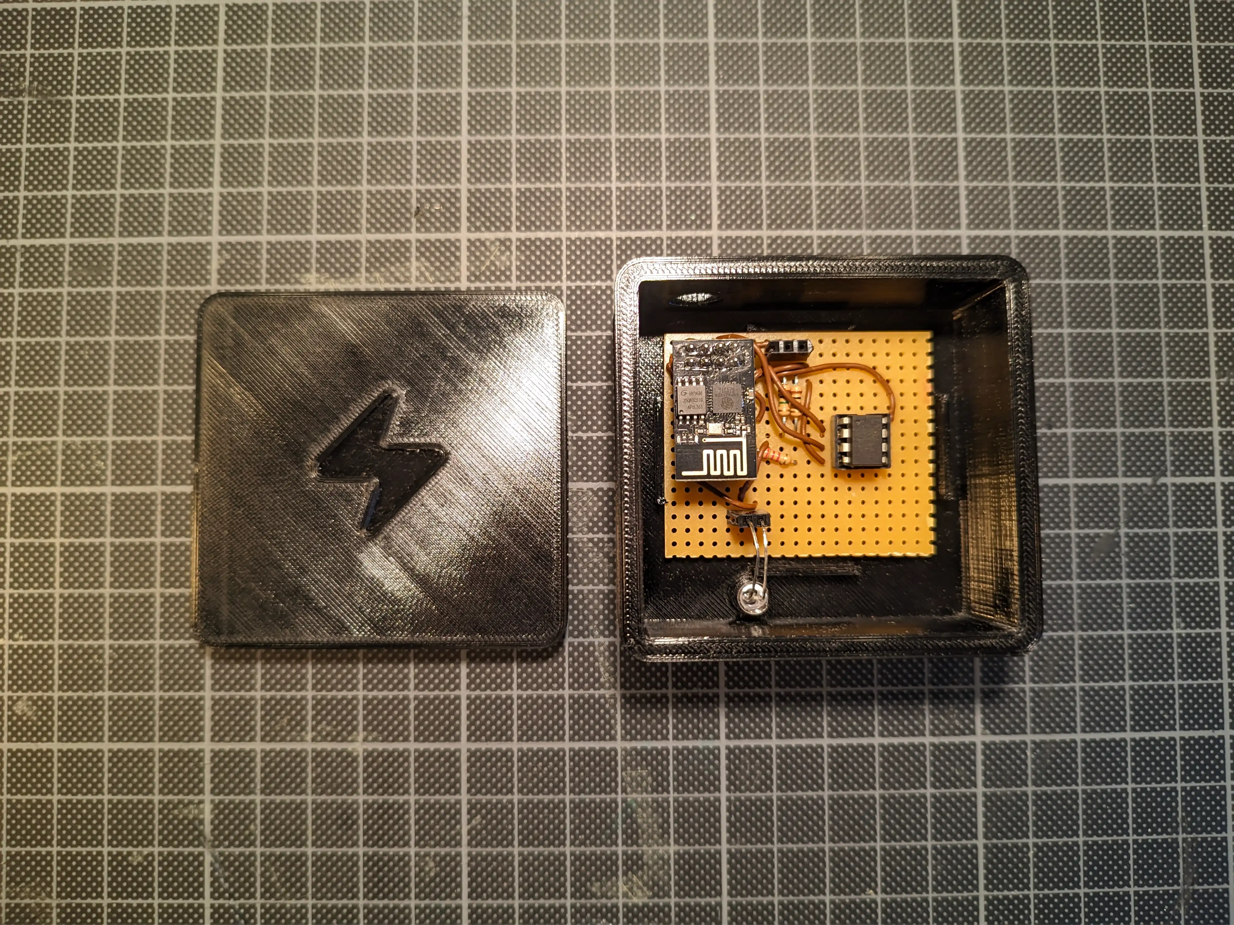
- ESP-01 microcontroller
- Attiny85 microcontroller
- BPW40 infrared phototransistor
- LM358P op amp
- 2x 1MΩ resistor
- 1x 2KΩ resistor
The additional Attiny85 microcontroller is required because the ESP-01 does not have a built-in brownout detector. Because of this, the ESP does not boot properly when the battery voltage drops below a certain threshold, causing it to overheat. Additionally, the ESP-01 does not support waking up from deep sleep without an external interrupt, unless I manually bridge two tiny contacts on the chip itself.
In my case, I also needed an op amp because the electricity meter is behind a plastic window, and the signal captured by the phototransistor was not strong enough for the ESP to reliably read the data without any amplification.
🧩 Overview
The Attiny85 is flashed with the firmware found in the attiny_firmware/ directory. Its only job is to turn on the ESP-01 every few minutes (the default is 5 minutes) using the ESP's CH-PD pin, make sure the ESP boots up properly (GPIO 3 is set to HIGH) and then turn the ESP back off if it fails to set GPIO 3 to HIGH within 200ms or if the ESP is done.
The ESP-01 is flashed with the ESPHome firmware (using the energy-meter.yaml configuration file). During startup, it sets GPIO 1 to LOW to notify the Attiny that it has successfully booted. Then, it connects to WiFi, waits for an SML data transmission from the smart meter on the UART RX port, publishes the states to MQTT, and sets GPIO 1 back to HIGH to signal to the Attiny that it is done. The ESP also measures and sends its own input voltage, which can be used to estimate the remaining battery capacity.
As a power supply, I am using a battery pack of three rechargeable AA batteries. With a five-minute update interval, the batteries last about one month before needing to be recharged.
🔬 Schematic
(KiCad Schematic, PDF Version)
📦 3D-Printed Case
The case was designed in FreeCAD. Both the FreeCAD project file and a .3mf file are available.


